
 中文 (中国)
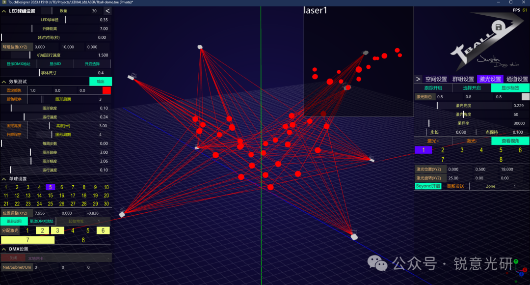
Tball is a software specifically for laser tracking of LED kinetic balls. Tball is based entirely on a three-dimensional physical space algorithm for laser tracking. It can track based on the lifting speed of different lights, which means it is equivalent to precise tracking based on four-dimensional parameters (three-dimensional position plus mechanical performance parameters).
System Highlights:
- Hardware: Tball also directly interfaces with Beyond, outputting laser data to the corresponding Zone in Beyond. Therefore, the hardware used for connecting lasers is the official Beyond hardware, either the FB3 or FB4 box.
- Software: Tball supports Artnet signal input and output. The input signal is used to calculate the three-dimensional position of the LED ball in real time and output the tracking point to various laser lights. The output signal is used for effect testing during debugging. It supports simulation rendering using D2 or D3 software. The default channel table for the LED kinetic ball uses the built-in lifting ball light library in Depence, but you can also modify the channel mapping as needed.
Since the software is based on a three-dimensional physical space algorithm for laser tracking, when debugging on-site, you need to use a laser rangefinder to accurately measure the installation position of the lifting ball and the three-dimensional position and angle of each laser light mirror.
In the software, you can arrange the lifting ball group in linear, grid, and circular patterns, and you can also make individual position adjustments for each lifting ball.
Function Introduction
Firstly, the software is divided into groups based on Artnet domains (Universes). One domain (i.e., 512 channels) is one group, and each group includes LED balls, laser lights tracking these LED balls, and related parameters. If you need to use the same laser light for cross-domain tracking, you only need to assign the same Beyond output Zone to the laser light in the same position in different groups. The left side of the software is the LED ball group debugging area, the middle is the effect preview screen, and the right side is for group settings, output settings, and interface-related settings. The upper right corner is the LOGO area, and the upper right corner displays the software’s operating frame rate. You need to ensure that the computer hardware configuration can run this software at a frame rate above 30 FPS. The LOGO circle is the project save button, where you can manually save the project file. The coordinate system navigation icon at the bottom right of the software indicates that the software’s coordinate system is a right-handed coordinate system (i.e., the blue Z-axis is positive towards the operator), which is opposite to the Z-axis direction of Depence’s left-handed coordinate system. Therefore, when using Depence for software simulation, the Z-axis coordinate position needs to be inverted accordingly.
For Depence simulation, I will provide corresponding example files with modified lifting ball and laser light libraries. You can also compare the light positions and corresponding rotation parameters in the Tball software as a reference.
In the software’s parameter adjustment areas on the left and right, you can manually click the up and down arrow buttons on the far left of all white title bars to expand or collapse the parameters of the corresponding sections. The left and right arrow buttons on the outer sides of the top title bars on the left and right are used to show or hide all parameters of the corresponding sections. All green buttons in the interface are toggle-type buttons, and orange buttons are point-control-type buttons, such as the fixed color button. Earth yellow text is for parameter labels, light yellow buttons are for multi-select buttons, and yellow text with a purple background indicates single-select buttons. Purple parameters are globally unified parameters, such as local network card selection. For all numerical adjustment parameters, you can adjust them by scrolling the mouse wheel. Of course, you can also manually enter data in the corresponding numerical area. Holding down the left mouse button in the corresponding numerical input area will trigger the corresponding differential adjustment menu. Placing the mouse over the corresponding adjustment difference area allows you to adjust the value left and right. When you right-click in these parameter slider areas, the corresponding parameters will automatically reset to their default values. Operations on the middle three-dimensional view are similar to those in other three-dimensional software. You can use the mouse wheel to zoom the view, hold down the right button to pan the view, and use the left mouse button to rotate and inspect the view. When the corresponding selection option is enabled, you can also use the mouse to select laser lights and LED kinetic balls and adjust their parameters accordingly.
The keyboard operation is similar to that of a game engine. The ASDW keys move the view left, back, right, and forward, respectively. The QE keys move up and down. The H key is for the Home view, and L, R, and T are for left, right, and top views, respectively. In the space settings on the right side of the software, you can switch the display and hiding of the coordinate axes, including adjustments related to UI parameters, which will not be repeated here. In the save project name field here, you can enter the file name you want to save. After clicking the save icon, it will be saved as the corresponding file name in the project folder. Next time, you can directly double-click this file to open the corresponding project.
Debugging Process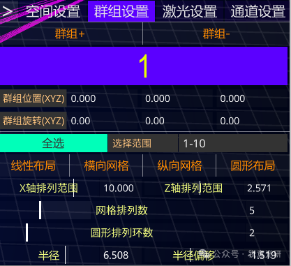
1. When you open the software, there is a default Group 1. You can find the group settings on the right side of the interface. Click the Group + button to add a group, and the Group – button will delete groups greater than 1. You can adjust the number of LED lifting balls in Group 1 on the right side of the LED ball group settings column on the left. Of course, the number of channels occupied by LED lifting balls within each group cannot exceed 512 channels, which you need to pay attention to. The group position parameters are the global coordinates of the current group. The positions of all LED lifting balls and laser lights within the group are adjusted based on this position. By default, it is the coordinate origin. When you debug on-site, you also need to first determine the position of this coordinate origin, as this is related to the coordinate measurement of LED lifting balls and laser lights. Adjusting the parameters in the group rotation section will rotate all LED lifting balls and laser lights within the group based on the group coordinates. Next is the arrangement operation of the LED balls within the group. When the select all button is activated, the selection range column is disabled, and all LED balls within the group will be arranged. If you only want to arrange part of the LED balls within the group, you can deactivate the select all button and enter the selection range in the selection range column, such as 1-10, which means arranging the LED lifting balls with ID numbers 1-10 within the group.
After adjusting the corresponding X-axis and Z-axis ranges, click the linear layout to arrange them linearly within the specified range on the corresponding coordinate axis. For example, setting the X-axis arrangement range to 10 will arrange them within the range of -5 to 5 meters on the X-axis.
If you want to arrange in a grid pattern, you can first adjust the number of columns for the grid arrangement and then click the corresponding grid arrangement button. Note that the X-axis and Z-axis arrangement ranges also need to be adjusted accordingly so that you can arrange in a grid pattern within the specified range.
For circular arrangement, you only need to adjust the number of rings for the circular arrangement, the base radius, and the radius offset, and then click the circular layout.
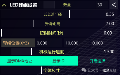
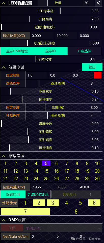
2. After arranging the LED lifting balls, you can next set the parameters related to the lifting balls on the left side of the interface.
You need to ensure that the lifting distance and speed of all LED lifting balls within a group are consistent because all parameters in the LED ball group settings section are global parameters. If your lifting ball control console is relatively far away, there may be corresponding signal delays. In this case, you can adjust the delay time to match the laser signal with the lifting ball signal. Usually, when simulating in Depence, you can keep this delay parameter at 0.
Each group of LED lifting balls can adjust the global installation position of the ball group through the ball group position option, mainly adjusting the Y-axis, that is, the height value. This height value is the height of the ball center when the lifting ball is fully raised. When debugging on-site, you only need to measure the bottom height of the ball and add the ball’s radius. In Depence, you can place a ball object at the position of the lifting ball to obtain the actual height of the ball. The unit of mechanical operation speed is meters per second, which you can find in the settings options of the corresponding light in Depence. Next are three toggle buttons to switch the display of each ball’s ID and DMX address in the three-dimensional view. When the selection is enabled, you can use the mouse to directly select a single ball to set the corresponding parameters. Font size refers to the size of the font for the ID and DMX address.
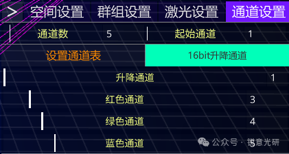
3. Next, let’s set the channel table mapping for the lifting balls. The default number of channels for the lifting ball is 5, which is based on the lifting ball light library in Depence. The default starting channel for the LED lifting ball group is 1. When the 16-bit lifting channel is enabled, it will automatically set the fine-tuning channel for the lifting channel to the next channel of the lifting channel. For example, if the default lifting channel is 1, the 16-bit fine-tuning channel is 2. You can map the remaining related channels based on the actual channel table of the light used. After setting, click the Set Channel Table button to complete the channel table mapping.
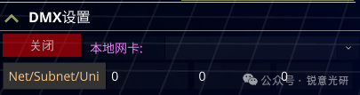
4. After the channel table mapping is set, if your computer is connected to an ARTNET box that can directly control the actual lifting ball, you can directly use the effect test area on the left side of the interface. Click the Activate Output button to enable the sending of ARTNET signals. Usually, there is no need to specify the local network card. If the output is not normal, you can first turn off the output and specify the network card for the output signal. Once the output button is turned on, the Input Enable button in the DMX settings at the bottom will be turned off, and the local network card option will be unavailable. The ARTNET network card is a global parameter. The Net/Subnet/Uni below can be used to specify the domain for receiving and sending Artnet signals for each group.
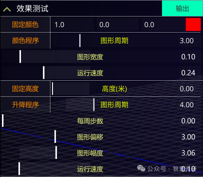
5. The effect test section is only used to test the basic functions of the lifting ball to ensure that it can operate normally. After activating the Output Enable button, clicking the Fixed Color will automatically set all LED balls within the group to the corresponding color. You can change the RGB parameters at any time. Their range is 0-1, and the results will be displayed in real-time on the right side.
Clicking the color program will automatically apply an effect curve similar to the MA effect curve to the color channels of the lifting ball. You can change the effect’s graphic period, graphic width, and running speed. When the speed is 0, the effect will be paused.
Clicking the fixed height button allows you to adjust the height of the lifting ball in combination with the graphic offset and height. When the graphic offset is 0, the height slider value is the operating height of the lifting ball. Of course, this height value is not the actual height. The actual height needs to be combined with the ball group position and group position parameters above. If the height is adjusted to 0, it means the lifting ball has descended to the lowest position. When adjusting upwards, if the value exceeds the travel of the lifting ball, it will not take effect.
When you click the lifting program button, an effect curve will be automatically applied to the lifting channel. You can adjust the graphic offset value, which is the middle value of the graphic operation, in combination with the graphic amplitude, graphic period, and steps per week parameters to create different effects. You can also adjust the running speed value to 0 at any time to pause the effect. This is more convenient for adjusting the laser angle when debugging the laser position with the lifting ball in a staggered position.
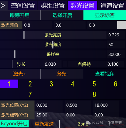
6. Next, we can set the parameters related to the laser lights. In the laser settings section, the first part separated by a horizontal line is the global settings within the group. After the tracking is activated, the laser lights will be assigned to track all lifting balls within the group. If you only want each laser to track different lifting balls, do not activate this option.
After activating the selection button, you can directly use the mouse in the three-dimensional view to select the laser to set different parameters for individual lasers. After activating the display label, the group and its own number where each laser in the group is located will be displayed above the light output port in the three-dimensional view. This way, you can understand the rotation state of each laser light. The laser color section is used to set the color of the laser light’s casing in the three-dimensional view. Laser brightness is used to adjust the output brightness of the laser lights within the group. For Depence simulation, appropriately reducing the brightness value will be more expressive. The laser angle here should be adjusted according to the specific angle value of the laser light you are using. The default value is 60 degrees.
The sampling rate should also be set according to the specific scanning rate of the laser light mirror used. The step length value and point hold usually remain at the default. The smaller the step length value, the more points can be drawn, of course, this is subject to the specific scanning rate of the laser light mirror. The larger the point hold, the brighter a single point will be. The default values here are set according to the performance in Depence software, and in actual use, you can adjust according to the actual performance of the laser light. In the following section, you can use the Laser + and Laser – buttons to manage the number of laser lights and switch to select different laser lights to set different positions and rotation parameters for the laser lights. When debugging on-site, first determine the three-dimensional position of the laser mirror relative to the coordinate origin and a rough rotation angle value. For on-site debugging, we can then use the effect test section options to activate the lifting ball or use the console to light up the lifting ball. Then, in the single ball settings on the left side of the interface, assign different lasers to each ball. Because in actual use, some lifting balls may be blocked by other lifting balls and are not suitable for tracking by lasers in specific positions. The specific principle is to assign lasers to each lifting ball according to the proximity principle. When you turn off the tracking enable button in the laser settings section on the left side of the interface, remember to turn on the tracking enable button for the lifting ball that needs to be tracked in the single ball settings section.
In the single ball settings section, you can also make fine adjustments to the position of a single LED ball, including specifying a different DMX address. Be careful not to conflict with other addresses. After assigning the laser, let’s activate the Beyond enable button to send the tracking point to Beyond. Remember to set a different Zone for each laser light. You can click the view angle button in the laser settings section to activate the tracking view of the corresponding laser light. Ensure that the lifting ball tracked by this laser light is within its tracking range when it moves up and down. If there is an overrun, you need to consider re-setting the position and angle of the laser light.
After determining that the lifting ball tracked by the laser light is within its field of view, adjust the angle of each laser light to make the on-site laser tracking point aim at each lifting ball. At this time, the position of the lifting ball is best random. Similarly, after adjusting the rotation angle of each laser, we can make the lifting ball move to determine the actual tracking delay time and make fine adjustments to ensure the final perfect tracking effect.
Future Functions
The current software implements the core basic functions. In the future, it will further optimize and add more play effects. For example, the function of separately controlling the color of the lifting ball and the laser, the radar interaction function of the lifting ball, etc. Suggestions from teachers and colleagues interested in this software are also welcome.