PL.Tracker v3.4 update instructions
Recently, we have made some significant adjustments to the PLTracker intelligent tracking system. We have abandoned the previous TouchOSC control interface and added support for the iOS platform. Now, you can use your iPad to control the computer lights.
Update Content:
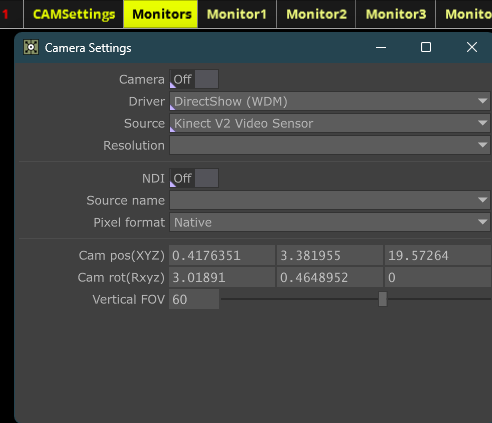
2. We have adjusted the camera settings. The new version currently only supports one camera connection. All operators will monitor the same stage image. If necessary, we will update and add the function to select the monitoring image in the future. You can click on the camera settings in the top title bar to adjust the parameters. Here, we have also placed the camera’s three-dimensional spatial position, rotation, and FOV parameters. For the camera and NDI camera settings here, the server will actually only connect to the last activated device.
3. To adapt to devices with larger screen spaces such as iPads, we have also adjusted the monitor allocation plan accordingly. Now, each control end has a separate monitoring screen. When you click on the monitor settings in the top title bar, 12 corresponding monitor setting buttons will be displayed. At this time, the settings related to the tracking target will be hidden. Clicking again will hide these monitor settings. You can click each button to set the corresponding monitoring screen and the three-dimensional space of the lighting fixture. After you connect the corresponding smartphone or tablet to the computer in extended screen mode, you can click the full-screen button in the corresponding monitor settings to open the corresponding control interface.
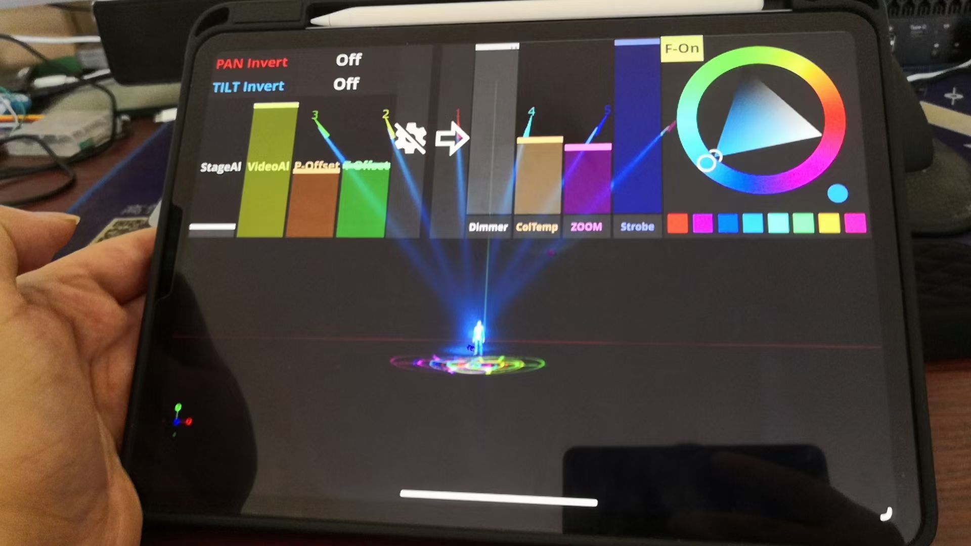
The figure below shows the iPad operation interface. Since the screen ratios of different devices are not the same, different versions are needed to correspond. For example, mobile phones usually have a 16:9 ratio. I have also covered the operation interface in full screen to facilitate operation. On the left side of the control interface are the adjustments related to the lighting fixture and the image. The two buttons on the left control the inversion of the PT axis of the lighting fixture.
The four sliders below are for adjusting the transparency of the three-dimensional stage, the transparency of the camera image, the offset of the P axis, and the offset of the T axis. When we integrate the three-dimensional stage with the actual camera image, we usually try to reduce the transparency of the three-dimensional stage image as much as possible. The three-dimensional stage image is a simulated image by the software, and its purpose is to make it easier for you to correspond the camera view with the virtual stage space. This way, even without turning on the light, you can clearly see the position of the lighting fixture on the stage.
Then there are the corresponding settings to close the button. It should be noted that for touch screens, due to the sensitivity, when you click the button and it does not respond in time, you can click and hold the button until it responds. This ensures that the operation is executed and there is no long response time. Of course, if you use a capacitive pen, there will be no such problem.
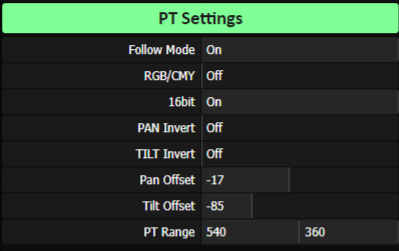
On the right side of the control interface are the lighting fixture channel operations. Unlike the previous version, the color channel has been upgraded from a slider operation to a color palette. Due to this change, the RGB/CMY color mixing mode switching option has also been added to the lighting fixture settings. You can switch according to the actual color mixing system of the lighting fixture.
In this color palette, you can directly click and drag the white circle on the outer ring to select a color. Click and drag the white circle inside to adjust the color saturation and brightness. When you adjust the color, the corresponding color will be output in real time. You can also click the round button in the lower right corner to save the adjusted color to the button below for easy retrieval.
The F-On/Off button in the upper right corner is the Follow mode switch. This button is not available in the M1 version. When you activate this follow function, other lighting fixtures will also be displayed on the corresponding control end screen. Of course, when it is not activated, only the current control lighting fixture screen will be displayed. On the server side, you can also directly enable the same screen display to enable the same screen display for all control ends.
Due to the change of the operation interface, the settings for OSC2, which was previously used for TouchOSC signal input, have also been deleted. Only the OSC settings for gyroscope data input are retained.
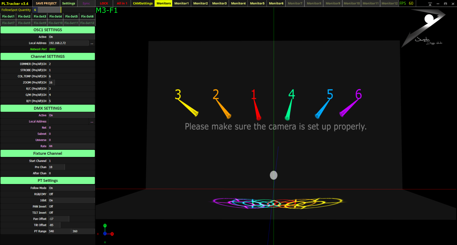
4. Regarding UI improvements, you can also use the mouse to operate the virtual view position and posture on the server. It also supports keyboard shortcuts ADSWQE for left, right, back, front, and rotation operations. Mouse operations are limited to left-click dragging and scrolling. This makes the operation more direct and effective. To facilitate the identification of the current object being operated, I have added the number of the currently activated monitor and lighting fixture in the upper left corner of the monitoring interface. M represents the monitor, and F represents the lighting fixture.
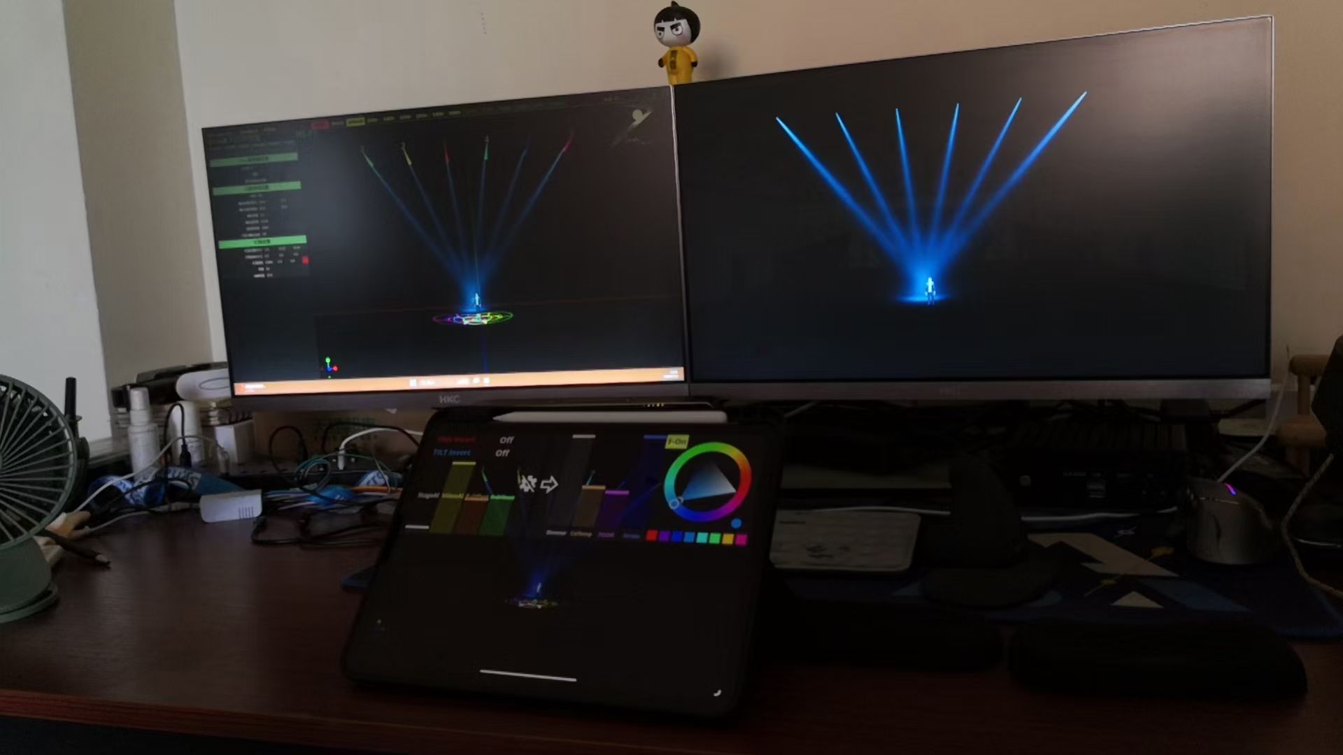
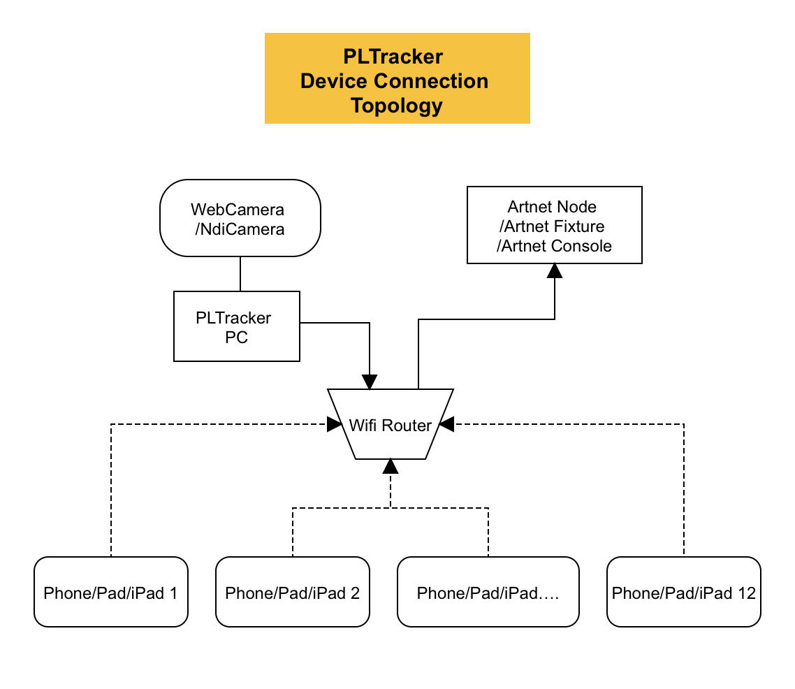
5. Regarding device connections, the following are the relevant connection diagrams. For the selection of wireless routers, it is recommended to use a gigabit router to reserve sufficient network bandwidth for related data transmission. If only one device is connected, a regular router can also meet the requirements. The monitoring screen connection of the control device is an extended screen of the server. The server monitoring screen ID is 0, and the subsequent extended screen IDs are 1, 2, …, adding up to 11.