K1 V1.0 Release Notes
1. Built-in Two Keying Modes: S KEY and M KEY.
- In S KEY mode, you can enable the Pick mode to sample the green background in the main window. Then, click the HSL Adj button under S KEY to open the parameter dialog for adjustments. In this mode, the sliders for the black background are not usable, except for the 2th Denoise secondary denoising.
- M KEY is used for situations with severe light spillage and when S KEY cannot meet the requirements. It offers the maximum degree of adjustment freedom.
2. Five-Channel Video Input/Output and Recording: Supports input from various brands of capture cards and video devices, and allows multi-channel synchronized input and output. Output supports NDI and video cards. Through AJA or Deltacast brand video output cards, it supports Genlock frame-locked output and allows checking the Genlock status. Each channel has two sets of outputs: the regular keying image/original camera image (FinalKey/Origimg) and the mask image. The regular output can also switch to a composite foreground/background image.
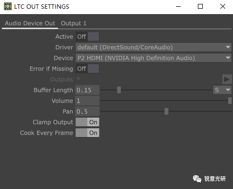
3. Video Recording with LTC Timecode Signal: Frame rate formats can be selected through the FPS drop-down menu.
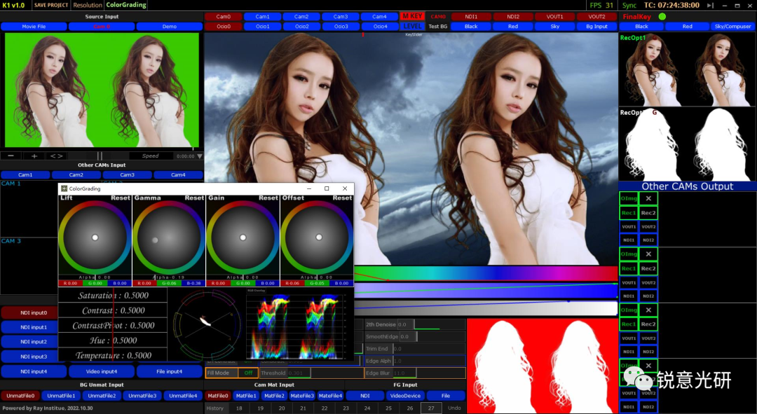
4. Support for OCIO Color Space Conversion and Keying Image Color Adjustment.
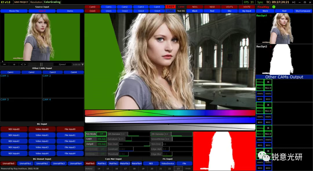
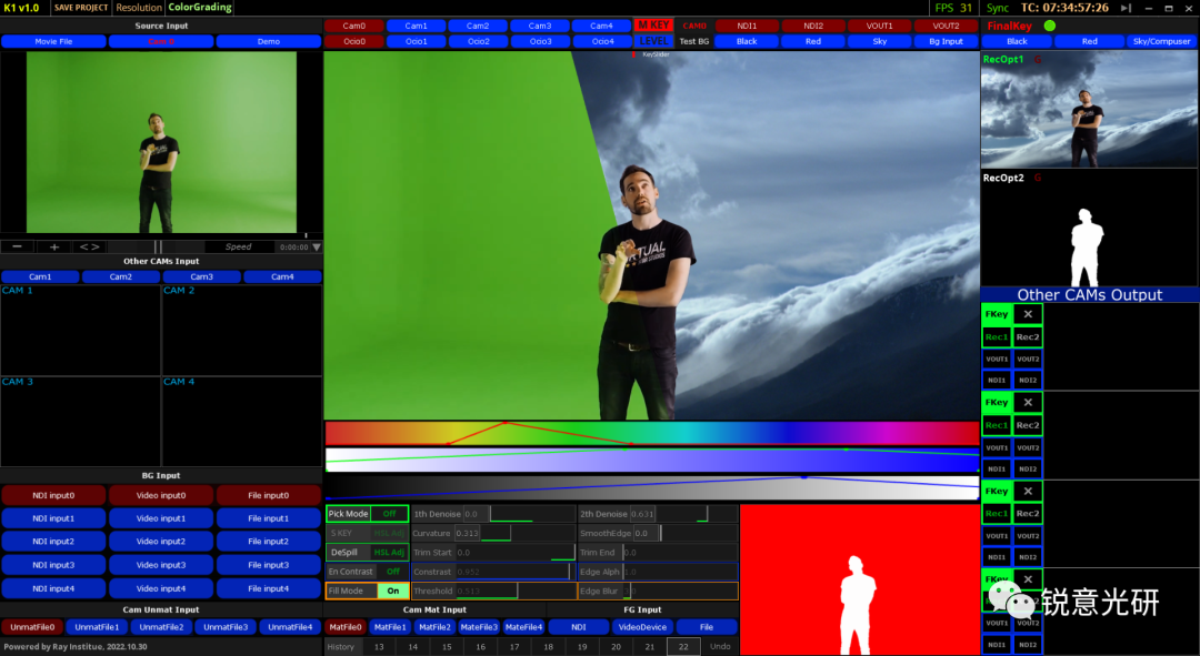
Software Interface Layout:
- The top is the software title bar. The Save Project button is used to save project files. Resolution is used to set the final resolution of the output video. ColorGrading is used for color grading of the keying image, which is also applicable to other camera images and is a global setting. FPS can be clicked to select the corresponding timecode frame rate format. This frame rate setting will also change the frame rate of the recording options. The Sync button is used to synchronize the CAM0 camera input timecode to the LTC output. By default, without synchronization, the software will automatically generate LTC timecode. Clicking on this timecode will open the LTC output settings interface.
- On the left side of the main interface, there is the video input source selection. Local green screen videos can be directly dragged and dropped into the Source Input window in the top-left corner for playback. Clicking the CAM0-4 buttons will automatically switch the corresponding video source to the main image in the center of the interface for keying operations. The CAM0-4 buttons at the top of the main interface can open the corresponding parameter settings windows.
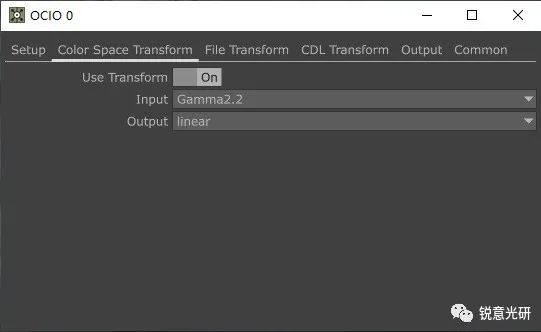
- The OCIO0-4 buttons are mainly used for color space conversion of the corresponding camera images. This is a professional photography-related technique, which can be simply understood as converting other color spaces into the Linear linear color space used by the computer’s 3D engine. Different brands of cameras can use different configuration files, and of course, you can also use the corresponding LUT for color grading. For detailed functions, refer to the TD documentation: https://docs.derivative.ca/OpenColorIO_TOP.
- The BG Input button in the lower-left part is for background material input, supporting NDI/video card/video material or image input as background input. When the corresponding background input is activated, you can click the BG Input button in the Test BG on the right side of the main interface to view it. The right-side panel can activate the SKY/Compuser button to output the composite image.
- The Cam Unmat Input section is for selecting protection mask materials. It only supports the import of black and white images to protect areas in the green screen image that do not need keying, such as green props. By default, if not enabled, select the Black image included in the software directory. The Cam Mat Input section is for selecting garbage mask materials. It also only supports the import of black and white mask images to remove unwanted objects in the camera image, such as ceiling lights.
- The FG Input is for foreground material input, supporting NDI/video card/file input. This input will be applied to the composite of all five video channels. If you do not want to enable it, you can switch to the NDI or video card option.
Main Interface Section
- The top-left part of the main interface includes options for camera input parameter settings and OCIO-related settings. The S KEY button in the middle can switch between different keying modes. LEVEL is for adjusting parameters of the corresponding camera image. Below that is a small KeySlider slider. You can directly drag this red slider to compare the keying effect. Of course, you can also achieve the same effect by dragging the mouse in the main window below without enabling PICK MODE.
- The top-right part of the main interface is for output settings of the CAM0 main camera. The options in Test BG can switch different backgrounds during keying to check the keying effect. The final keying effect is largely related to the actual on-site lighting conditions. The on-site lighting must be as close as possible to the lighting conditions in the background material to achieve better integration. Note that only the BG Input option will affect the final output here.
- Below the main image is the adjustment bar for hue, saturation, and brightness values in M KEY mode. Usually, when you switch to M KEY, the adjustment lines will turn into red, green, and blue. When you activate Pick Mode, you can click and drag in the green background of the main image to select the color range to be removed. The adjustment lines will usually be set automatically, but you can also fine-tune them. To retain as much information from the original image as possible, it is usually necessary to make smooth adjustments.
- Further down is the main adjustment area for keying operations. In S KEY mode, only PICK MODE, S KEY, Despill, and 2th Denoise are available. In M KEY mode, only the options in S KEY are ineffective.
- PICK MODE can switch the background color selection mode of the main monitor image. When disabled, you can adjust the contrast slider between the original image and the keying image in the monitor image with the mouse. Both the main monitor image and the input selection pane in the top-left corner can be zoomed in or out by scrolling the mouse wheel. Pressing the H key will restore the original size display.
- The HSL Adj button under S KEY will open the corresponding parameter adjustment window. The first item is the background color you selected in the main monitor image. Color Tolerance is for color tolerance adjustment, which is a hard cut adjustment. Color Softness is for gradient adjustment. Usually, try to make flexible adjustments and check the keying effect in real-time to ensure that as much of the original image information is retained as possible. Value Multiplier is for brightness adjustment, and Dry/Wet Mix is for mixing the original image with the keying image. These two items depend on the specific situation. Sometimes, to get a finer effect, you need to adjust it to 0.5, usually kept at 1.
- Following that are the options for adjustment after secondary denoising. If you are not satisfied with the 2th Denoise adjustment, you can use these options below to get a clean background and keying image. The first item, Threshold, is for threshold adjustment. The usual setting is around 0.5. Of course, this adjustment aims to retain as much image detail as possible without considering the cleanliness of the actual background. The second item, Soften, adjusts the transition degree of the foreground and background images (black and white masks). It is usually set to 1. The last item, MinVal, is equivalent to a low-cut treatment for the image to obtain a clean background.
- The options in Despill are set for color spill removal. The specific options are similar to the HSL Adj adjustment options in S KEY, with the addition of a Skin Color adjustment. This item is specifically for adjusting the hue conversion of color spill at the keying edge. When the value is 0, all the options below can be used. The closer to 1, the less impact these options have on the image. When the value is 1, the color spill will be adjusted to a light yellow. The maximum value is 2, which increases the color saturation and leans towards a darker tone. This will also affect human skin color.
- 1th Denoise is the first denoising for removing background noise in M KEY mode. 2th Denoise is used in both keying modes.
- Curvature is for setting the curvature of the keying curve, which depends on the situation.
- SmoothEdge is for adjusting the softness of the keying edge. It is best not to set this option, as it will definitely cause loss of original image details.
- Trim Start/Trim End are for low-cut and high-cut processing of the image. They are kept at 0 by default.
- En Contrast is for enhancing the contrast between the foreground and background of the keying. You can adjust the edge contrast with the Contrast slider.
- Edge Alpha is for adjusting the softness of the edge transparency. These options are mainly used to handle edge white fringes.
- Fill Mode is for remedying severe color spill. When this is enabled, the mask window on the right will display the adjustment results of the related options. You can adjust the threshold to include the areas removed by color spill. Edge Blur is used to soften the edges to get a better effect.
- The bottom part shows the history of parameter adjustments. You can click the Undo button to revoke the parameter adjustments.
Main Interface Right Side
- The first row is the recording options for CAM0. You can switch between recording OrigImg (original green screen image) and FinalKey (keying image). The green recording button is on the right.
- Below that is the option for overlaying the background after keying in the main monitor image. The default is Black, and this option will affect the final output. Sky/Compuser is for composite image output.
- The two panes below are the two modes of the main monitor image: final output and MASK view. Clicking the button in the top-left corner of each will open the corresponding recording options. The first item, RecOpt1, depends on the selection mode of the CAM0 recording image above (original image or keying image). By default, the recorded video files all have LTC timecode. The second item, RecOpt2, records the MASK view content, which also has LTC timecode. By default, all the purple content in the second item follows the settings in the first item. When you click the green circular recording button, both of these views will be recorded simultaneously. You can manually set the naming by clicking the gray File button in the figure below, or click the green button to keep the default naming rule. Of course, you can also cancel the simultaneous recording of this MASK content by clicking the gray button in the red frame of the Record item. For the parameter description of this recording window, refer to the TD official documentation: https://docs.derivative.ca/Movie_File_Out_TOP.
- To the right of the RecOpt option, there is a dark red G indicating the Gen-Lock output status of the main monitor window. Dark red means it is not enabled, and green means it is activated. You can switch different camera images to the main monitor window to check the Gen-Lock status of the video card output for the corresponding camera image. To enable the Genlock function, you need to use a video output card from AJA or Deltacast brands and select the reference source in the Reference Source. The First Field option is already bound to the field settings of the capture card input, so the corresponding options are displayed here. For related option descriptions, refer to the TD documentation: https://docs.derivative.ca/Video_Device_Out_TOP.
- The lower pane shows the output monitoring of the four fixed cameras. The green-framed button on the left is similar to the recording option for CAM0. The first button, OImag, indicates recording and outputting the original image. If you want to record the corresponding camera image at the same time when clicking the recording button, you can switch the X button to ✔. The purple content in the two REC recording options also follows the settings in CAM0’s RecOpt1. The blue-framed button is for video card and NDI output settings. The NDI output settings here all follow the NDI1 settings of CAM0. Video card output can activate the corresponding Sync outputs for synchronized output. For video card output settings, refer to the TD documentation: https://docs.derivative.ca/Video_Device_Out_TOP.