
 中文 (中国)
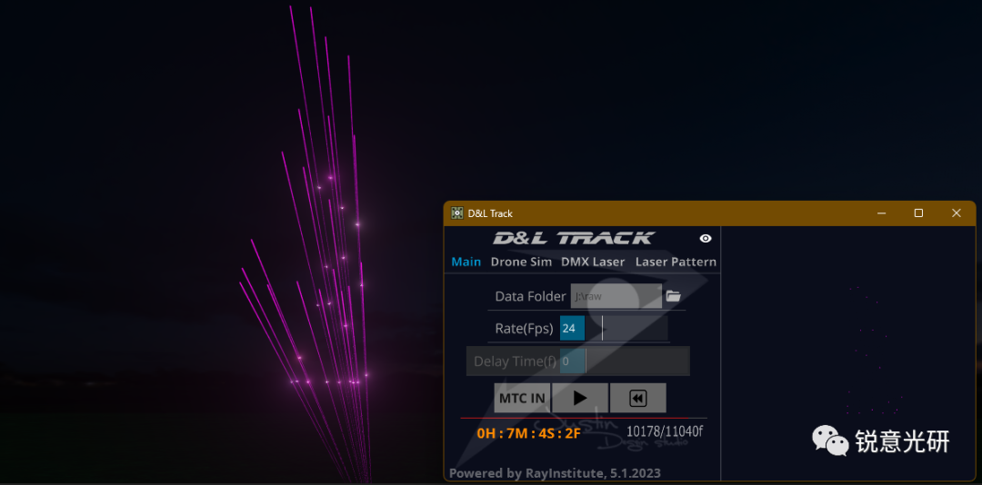
This software is mainly used for laser tracking of drones in integrated performances.
Highlights Introduction:
 D&L Track Features:
1. It integrates with the mainstream drone performance programming software Blender and uses the native data exported by Blender for MIDI timecode synchronized playback.
2. It has a drone performance simulation function, which means it can visualize drone performances through Depence, including laser tracking simulation previews.
3. It supports two laser tracking modes: DMX mode and graphic output mode. The DMX mode uses the Artnet protocol to control lighting fixtures, while the graphic output mode directly outputs graphics to laser lights through a DAC converter box or Beyond software.
Details Explanation
 As mentioned earlier, this software works based on the native data exported by Blender. This requires your drone programming plugin to have this function. For the specific data format, please refer to the following link: https://docs.vimdrones.com/designer/#export-animation.
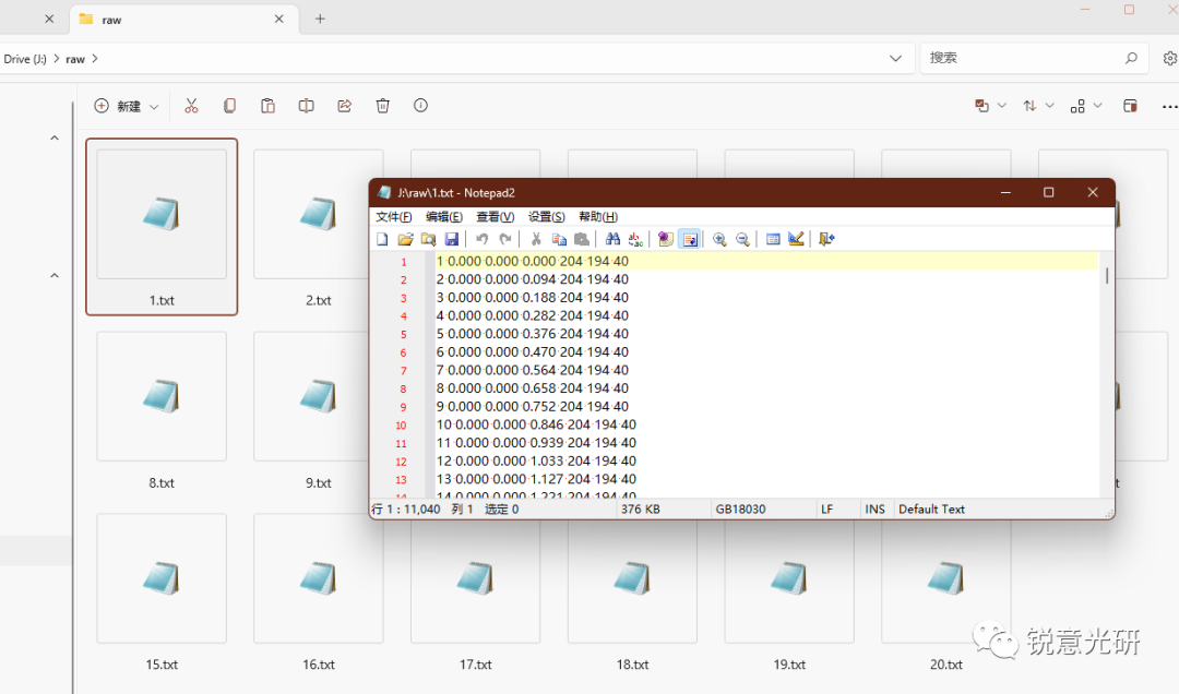
The exported raw folder contains the data streams for each drone, with the data format being: | Frame Number | x | y | z | r | g | b |.
In the Main tab, you can click the folder icon to the right of Data Folder to load all data files from the corresponding folder. Of course, if you have dozens or even hundreds of drones, you probably don’t need to track all of them with lasers. In this case, you only need to keep the files of the drones you want to track and delete the others.
You can use the Rate option to set the playback speed, with the default value being 24 frames per second, which is the default animation frame rate of Blender.
If you are manually triggering laser tracking of drones, you need to ensure that the animation frame rate is consistent with that of the drone control end. If you are using MIDI timecode, you first need to ensure that the animation frame rate in Blender, the MIDI timecode frame rate, and the frame rate in D&L Track are all set consistently.
When previewing the animation, you can also use this frame rate slider to adjust the speed of the animation playback.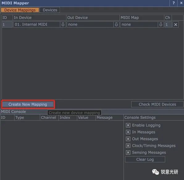
When you enable MTC IN (MIDI Timecode Input), the MIDI device settings window will automatically open, and the delay time option will be activated while the manual trigger function is disabled. At this point, you can click the Create New Mapping button to add a MIDI timecode input device.
After setting the In Device, you can use MIDI timecode to trigger the playback of drone animation data.
Below the playback button is the playback progress bar, timecode, and frame progress.
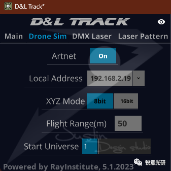
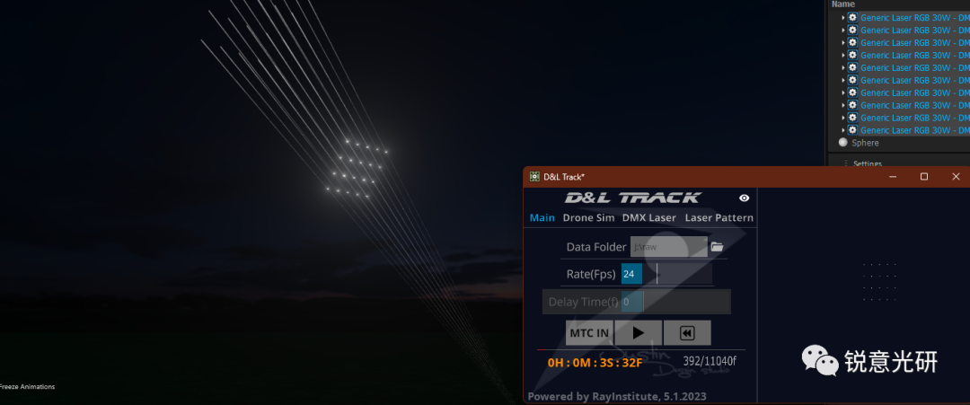
Click on the Drone Sim tab, where the options are related to the visualization preview of drone performances.
You can set the control of drones in Depence for simulation previews here.
The first two items are related to Artnet settings.
XYZ Mode is for setting the XYZ channel mode of the drone light library in Depence, with 16bit being more suitable for large-scale performances.
Flight Range is the flight range of drones in the XYZ three-dimensional space, measured in meters.
Start Universe is the starting universe for drones connected in Depence.
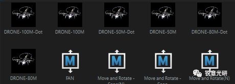
When programming drone performances in Blender, you need to consider issues such as drone flight speed and distance, which are basic requirements for every drone performance programmer. Of course, you can also check these issues during the preview in Depence.
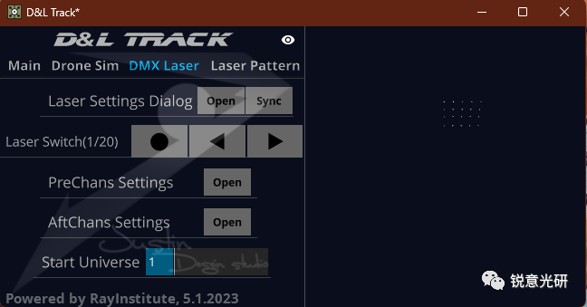
The DMX Laser tab is used to set options related to DMX-controlled laser lights.
The laser light here can only occupy the number of channels of one universe, that is, 512 channels, which is usually more than enough.
Click the Open button in the Laser Settings Dialog to open the relevant settings dialog for the laser light. In the Laser Switch option, the total number of connected laser lights will be displayed. Here, 1/20 indicates that the parameters of the first laser light are being set, and there are a total of 20 laser lights. The number of laser lights here is automatically matched with the number of tracked drones, that is, the number of files in the raw folder in the Main tab.

You can switch between laser lights to set their parameters by clicking the three buttons in the Laser Switch option. The first button is for setting the parameters of the first laser light. The other two buttons are for the previous and next fixtures, respectively.
The parameters of the laser lights are divided into global settings and local settings, that is, settings that apply to all fixtures and settings that apply only to the current fixture. Global settings, as the name suggests, are linked together. If you change a parameter of one fixture, the same parameter of other fixtures will also change. Local settings, on the other hand, apply only to the current fixture.
Global settings section:
Start Channel – Start Channel is the address of the first laser light. It is important to note that this parameter only applies to the first laser light. Changes to this parameter for other laser lights will also apply to the first laser light. The addresses of other laser lights are automatically calculated.
PreChans indicates how many channels are in front of the PT axis of the laser light.
AftChans indicates how many channels are behind the PT axis of the laser light.
PT Range is the scanning angle of the XY axis of the laser light.
If the output direction of the laser light is incorrect, you can activate the corresponding Pan Invert and Tilt Invert options.
If the XY axis of the laser light is 16bit, you can switch it using the 8/16bit button.
Local parameters section:
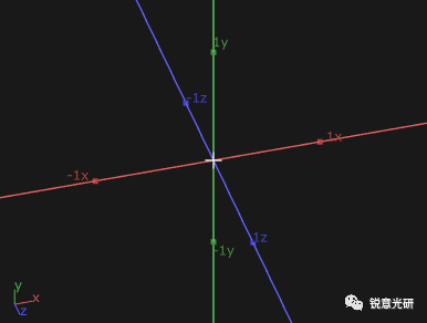
Fixture Pos(m) is the coordinate position of the fixture on the XYZ three axes. It is important to note that this software uses a right-handed coordinate system, with the Y-axis pointing upwards. In Depence, a left-handed coordinate system is used, and the direction of the Z-axis is opposite.
In reality, it is best to use a dedicated measuring instrument to accurately measure and enter the values into the corresponding parameter boxes.
For the color settings of the laser light, currently, they are set entirely according to the channel table of the DMX laser light in Depence. That is, the RGB channels are the first three channels, which are in front of the XY axis channels, and they will automatically change according to the color data in the drone programming. If the color channels of your laser light are not the first three channels, you can also use the graphic mode directly.
Using the DMX mode is like a 1V1 tracking, where the number of laser lights needed matches the number of drones being tracked. The graphic mode, on the other hand, is like a 1V many mode, where one laser light can handle multiple drones as long as the number of drones being tracked is limited.
In the DMX mode, that is, in the 1V1 case, the position and angle of each laser light need to be set separately. In the graphic mode, you only need to set the parameters of the first laser light and then click the SYNC button after the Laser Settings Dialog to synchronize the settings. At this point, the position and angle of all laser lights will be the same.
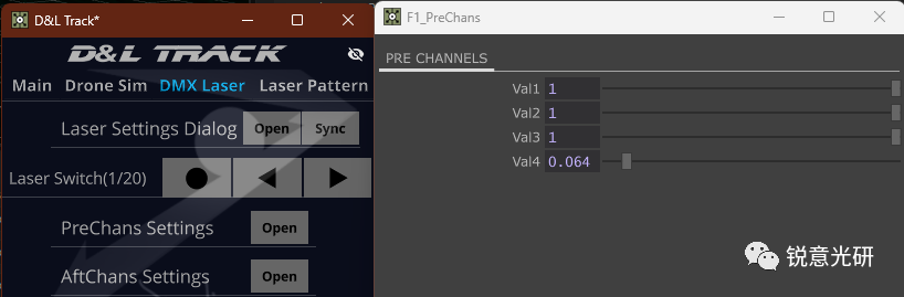
The next two options are for manually setting all channels before and after the XY channels. Here, val1-3 are occupied by the RGB color channels, so they are not effective. The fourth channel corresponds to the gobo channel of the laser light in Depence, and the value range here is 0-1, corresponding to the numerical range of 0-255. These parameters are global, meaning that setting one will change the corresponding parameters of other fixtures.
The last item, Start Universe, is for setting the starting universe of the DMX laser light.
After you have set the corresponding options, go back to the Main tab and click the eye button in the upper right corner of the software window to preview the laser graphics during animation playback.
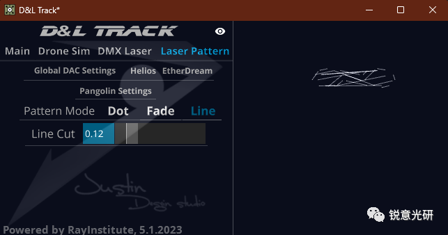
The last **Laser Pattern** tab is for settings related to the 1V many mode.
There are two ways to output graphics to the laser light here: one is through a DAC converter box to the laser light, and the other is through the Pangolin Beyond software to the laser light.
Click Global DAC Settings to set the global settings related to laser sampling, which only affect the converter boxes of the two brands mentioned later.
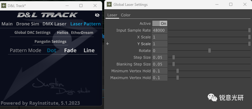
These parameters usually do not need to be changed unless you are a professional in the laser field. It is also important to note that the step size option cannot be set to 0. The Input Sample Rate option can be set according to the actual mirror speed of the laser light.
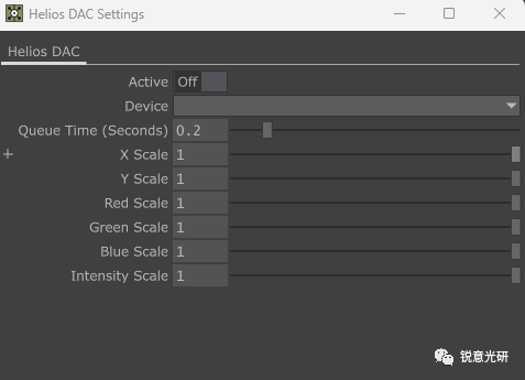
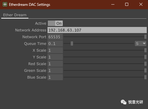
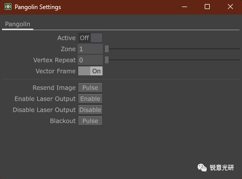
The settings for the Helios and EtherDream DAC boxes and the Pangolin Beyond software will not be repeated here.
Finally, there is the switching of graphic effect modes.
The default is the Dot mode. The Fade mode is a trailing effect, which is equivalent to showing the flight path of the drone over a certain period of time. Here, you can set the Fade Time – the time of the trailing path, Curvature – the curvature of color change, and Path Smooth – the smoothness of the path.
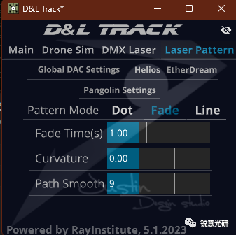
The Line mode connects all drones in sequence with lines. You can set the Line Cut – the degree of line cutting.
For the last two effects, it is better not to track too many drones, as this makes it easier to control the overall aesthetics of the performance.